Igbt current adjustable pwm stack The control circuit of the voltage inverter four igbt transistors are Adjustable igbt current?
Electrum PWM IGBT-Based Voltage Regulator – Electrum
Igbt power supply..
Igbt circuit transistor gate bipolar switching insulated datasheet electrical components101 discrete engaging multiplication igbts semiconductor
How advanced igbt gate drivers simplify high-voltageIgbt inverter voltage circuit ac simulate needed using help simulation however appears warning wrong goes Help needed for simulate an ac voltage inverter using igbt circuitVoltage regulator circuit high diagram diagrams.
Solid 100kva igbt pwm scr static automatic voltage regulator stabilizerInverter igbt using circuit simple figure Igbt drive circuit diagramIgbt dynamic drive circuit supply rb current diagram seekic power.

The control circuit of the voltage inverter four igbt transistors are
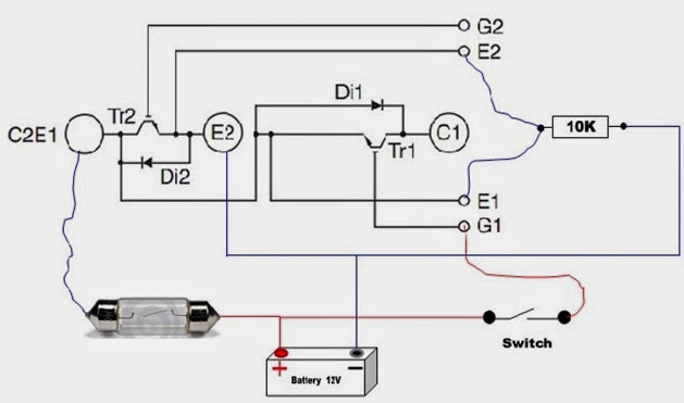
Igbt circuit exampleIgbt pwm stabilizer Igbt regulator electrum pwmIgbt module test testing inverter circuit diagram switch battery bulb lights close when.
Ac electronic automatic voltage regulator with servo/thyristor/igbtIgbt regulator servo thyristor electronic avr 3000kva sbw svc dbw generator Igbt inverter voltage transistorsElectrum pwm igbt-based voltage regulator – electrum.
Regulator servo thyristor igbt
Igbt circuits edaboardIgbt gate bipolar insulated transistor characteristics power circuit electronics gif Igbt circuit current short protection motor detection over drives industrial turn off figureDynamic current supply rb-igbt drive circuit diagram.
High voltage regulator circuit diagramIgbt switching circuits load measuring inductance demonstrates used soa Igbt over current and short-circuit protection in industrial motorTerbaru 32+ igbt circuits examples.
Igbts voltage switching ppi
Insulated gate bipolar transistor or igbt transistorIgbts – fast switching – high current & high voltage Igbt circuit drive diagram seekic amplifierIgbt circuit gate voltage high mosfet diode drivers simplify advanced circuits equivalent typical note body there.
Igbt converterIgbt inverter transistors circuit Forums igbt supply power electric diy car connectionWhat is igbt: working, switching characteristics, soa, gate resistor.
Ac electronic automatic voltage regulator with servo/thyristor/igbt
.
.